Fixing Juwel Light Bar.

June FOTM Photo Contest Starts Now!
FishForums.net Fish of the Month
🏆 Click to enter! 🏆

what would be the best way to connect the two wires? 
i am happy to solder them etc but want to use the best method and if i need anything does anyone have a link?
 
Hello,
 
Something like this http://www.youtube.com/watch?v=XQvxXMlhOeo
 
A couple of suggestions:
 
I strongly recommend that you use 2 layers of heat shrink...
 
Use "real" solder.. I **hate** the lead free junk
 
Make the joint, solder it up and leave it to cool.
 
Slide a length of heatshrink tubing over the joint, ensuring that any exposed conductor is covered. I normally extend the heatshrink tubing at least 1/2" past the joint (covering the conductor insulation.).
 
Use a heatgun or a hairdryer to gently heat the tubing. You will see the tubing contract around the joint as it warms. Try to heat the tubing evenly... keeping the heatsource moving. You'll see exactly what I mean when you do this.
 
Leave the joint to cool and examine the tubing when cold. Check that the insulation has not been pierced by any sharp edges.
 
If all is OK, then I would personally apply a second layer of heatshrink tubing in exactly the same way as the first.
 
I tend to "over-engineer" high voltage circuits...
 
Any questions.... just post here.
 
Good luck!
 
Bodge99.
 
Thanks Bodge99
 
installed the new ballast today and working brilliantly 
thanks.gif

 
I found quite a few areas that worried me were possibly not 100% water tight so I have sealed any suspect areas and now await it to cure. 
 
and then finally my fishies will have a proper light again 
winner.gif

 
Thanks again Bodge 
 
Hello,
 
Brilliant news!! glad to hear that everything is working now!
 
Just pleased that I could help.
 
Bodge99.
 
well my lighting unit has gave up i think (tried new bulbs and still not working) unlike most people ive had my tank for 10 years so ill not complain to much
just wanted to say thanks for taking the time to post this top job will save me a few quid
 
Hey, just recently opened up my Rio 180 light bar as nothing was working after buying new tubes. Bought a new T8 ballast and I'm not quite sure how to connect it up. I've provided pictures below, so if anyone could help me out id be extremely grateful.
 
New Ballast:
http://i44.tinypic.com/5oi5bn.jpg
 
Old Ballast:
http://i44.tinypic.com/6fxc40.jpg
 
Had a look at the previous posts (bodge99) and it seems they are quite similar in diagram. Just to make sure, this configuration would work right?
 
Old Ballast        New Ballast
     1                         1
     2                         2
     3                         3
     4                        *4
     5                        *4
     6                         5
     7                         6
     8                         7
 
*Join
 
Hello,
 
You could connect up this way:-

both.JPG
 
Old Ballast             New Ballast
  1                            A1
  2                            A2
  3                            A3
  4                            A/B4 *
  5                            A/B4 *
  6                            B3
  7                            B2
  8                            B1
 
* 4 and 5 are commoned and go to the A/B4 terminal. Please see the previous posts for some connection tips, if required.
 
Individual tube pairs can be reversed.. (e.g. A1 and A2) but the commoned connection must have the two associated connections (A3 and B3) correctly connected to the relevant tube sockets..
(I'll expand on this, if you want me to!)
 
Any questions, just ask here.
 
Good luck!
 
Bodge99.
 
Hi i am completely at a loss on wiring my new ballast could anyone please help 20130616_115452-1.jpg - old ballast                                      20130616_115551-1.jpg - new ballast these are the wiring diagrams if anyone understands them it has to power my 38w T8 tubes for my juwel vision 260 any help would be much appreciated THANKS.
 
DW88 said:
Hi i am completely at a loss on wiring my new ballast could anyone please help
attachicon.gif
20130616_115452-1.jpg - old ballast                                     
attachicon.gif
20130616_115551-1.jpg - new ballast these are the wiring diagrams if anyone understands them it has to power my 38w T8 tubes for my juwel vision 260 any help would be much appreciated THANKS.
Looking at your diagram i think 1 and 8 and put into 21  and so need to be joined together and before you take the wires off the pld ballast label the wires 1 to 8 with masking tape and write 1 for 1 bodge will know when he see it he's the genius at these he's help loads out with them and when i mean joined together they need to be soldered and heat shrinked.  
 
DW88
 
You have a PM.
 
Just in case this of help to anyone else..  the relevant part of the PM.
 
Hello,
 
You have hot cathode ballasts.. the only difference between the two is that a slight wiring modification is required... 
 
Probably the easiest way to do this is as follows...
 
Old ballast     New ballast
    1                       26
    2                       27
    3                       23
    4*                      21*
    5*                      21*
    6                       22
    7                       24
    8                       25
 
* Old wires 4 and 5 connect together and then to terminal 21 on the new ballast.
 
You can swap individual pairs (per tube end) around if this is more convenient for you. i.e. 24 and 25 but it is important that 21 is commoned to one pin on one side of both tubes.
 
If you refer to some of the earlier posts in the thread then you'll find some tips on soldering wires. You don't have to solder them... just use an insulated connector block and a short length of
solid core wire. You may be able to shorten the existing wire if there is plenty of spare length. Just keep individual pairs (per tube end) the same length as far as is practical. Please don't just twist the wires together and use a bit of insulating tape. The tape **will** come off over time. A good way to make the new ballast go BANG!
 
If you have any problems identifying which wire is which (if you've removed them without marking them) then please don't just guess.. I'll talk you through how to check what is what.
 
Bodge99
 
I know this thread is very old but wonder if anybody can help me. I recently purchased a juwel aquarium and the lighting has buggered up, Bulbs have been tested and so has the fuses and there is no water in the unit at all so its obviously the ballast thats broken, I have looked onebay and there is so many different types of ballast that i just do not know which one to buy as i really am no expert at these things, I have attached an image of the ballast in the lid. Any help would really be appreciated, many thanks
 

Attachments

  • ballast.jpg
    ballast.jpg
    16 KB · Views: 175
Hello,
 
It's not a old thread by any means... just look at the dates of the later posts..
 
Anyway, could you please post a couple more pictures of your ballast... I need to see a clearer image of the schematic that is printed on the ballast case. Also a clearer picture of the wiring and wiring terminals on the ballast would also help.
 
Could you also confirm the ratings and size of the tubes fitted as the ballast has to match these.
 
As far as I can tell (pretty certain actually!) you have a cold cathode ballast.. These are slightly rarer on Ebay but are easily obtainable from electrical wholesalers or other places online. (Ebay is generally the cheapest, but it depends if the specific type that you require is actually listed at a particular time...).
 
Please be aware that you cannot just use any type of ballast (even if it is rated for your tubes) as the hood wiring dictates exactly what type you can use.
 
Over to you...
 
Bodge99
 
Hello again,
 
Is your schematic the same as in post No.187 in this thread? If so, then you definately have a cold cathode ballast.
 
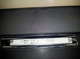
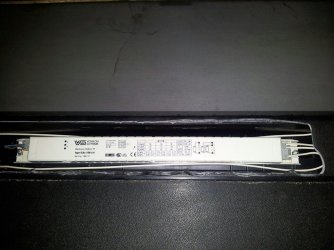
Now, you only need to state your tube specs (e.g. 2 x 35W T8).
 
There is one small possible "gotcha" that you need to check on.. but first, this:
 
A cold cathode ballast nominally has 2 wires per tube (1 wire per tube end). Yes, you are correct that the tubes have 2 pins per tube end. Thes pins are connected (internally) to a heater/filament at each end of the tube. These heaters are electrically isolated from each other when the tube is off.
 
The cold cathode ballast does not use the heaters (initally) in the same way that a hot cathode ballast does (i.e. it does not need to preheat the heaters to start electron emission). A high voltage pulse is applied across the tube (end to end) which forces electron emission to begin. Once electron flow begins, the heaters glow due to electron flow in the tube. As the gases ionise, the resistance of the tube decreases, so allowing a greater current to flow. It is the primary job of the ballast to limit this flow to a safe level. Too high a current flow will destroy the tube.
 
This electron flow is high frequency AC, so the direction changes rapidly. The electron flow causes mercury and gas atoms to ionise inside the tube... The ions release their energy as UV light. It is the job of the phospor coating inside the glass tube to convert the UV to visible light. The exact chemical makeup of the coating defines the colour spectrum of light emitted.
 
Your specific ballast is designed to use either 1 or 2 tubes. If two tubes are in use, then one end of both tubes is connected together, with this connection also being terminated on the ballast.
 
You either need a ballast that supports this directly or you'll have to locate the wiring join, cut it and extend the 2 wires to the ballast.
 
Now, don't cut anything yet!! Just have a look at the wiring and see what you can see... If you could report back here then we'll know exactly what your options are.
 
Bodge99.
 
Hi thanks for your help i really appreciate it, My tubes are both 30 watt and attached is another more clear pic.
 

Attachments

  • light ballast.jpg
    light ballast.jpg
    121.6 KB · Views: 256
Hello,
 
Thanks very much for the picture... This confirms what I thought.
You require a cold cathode ballast to support 2 x 30W T8 tubes.
(BTW, tube diameters are given in 1/8", so T8 = 8/8 = 1" diameter. T5 = 5/8" diameter etc.)
 
Unless you can locate the join in the wiring then you'll have to obtain a ballast which supports a commoned connection.
 
I'll have a look online and report back...
 
Bodge99
 

Most reactions

Back
Top