Mikaila31
Always Watching
This thread is focused on building a DIY light from scratch or retrofitting an existing fixture. A few methods I use may be uncommon and still somewhat unproven. The point of this build was to get the most light for the cheapest cost, but with maintaining good efficiency. Though with any DIY I am not responsible for any damage caused by constructing a DIY light.
To start with I have been using CFL ballasts to power linear tubes. By CFL I mean the spiral energy saver bulbs. This takes the cost of the ballast from being one of the most expensive part of a fixture to about $1-3. However it only works well with wattage below 23-26 watts since these are the more common larger sizes of CFL bulbs. You can certainly go higher, but the cost jumps quiet a bit. (for example 40 watt spiral CFLs tend to go for $8-10). This method also works best with T5 bulbs, these are closest to the diameter of the spiral compacts and also one of the more efficient linear tubes. However it is not limited to T5 bulbs, it works with T8's or power compacts. This method allows for a lot of customization including underdriving or overdriving bulbs, but I will go into more detail later.
I will only briefly cover mounting a fixture. Mainly because this is very variable depending on how you are mount the bulbs and to what.
First we will start with a brief overview of fluorescent lights. T8, T5, PC bulbs are all very similar in construction. The bulbs are powered by ballasts, which increase the voltage required to start the bulb. Wires then run to each pin of the bulb. They are pretty simple overall. The wiring can vary a bit depending on the individual ballast used. This is a general diagram of a linear bulb fixture.

Also common with T8 fixtures are the "starter" type. These function similar as above, except instead of a ballast they have a transformer. The Starter is a capacitor that functions to increase the voltage required to start the bulb.
Now for building your own fixture!
Step 1: locate a ballast
As I mentioned above I have been recently experimenting with using Spiral CFL ballasts to power other bulbs. This greatly decreases the cost of the fixture. You need to buy a spiral CFL with the proper wattage you want. For T5's and PC bulbs the wattages are basically equivalent. Example a 14 watt CFL ballast will power a 14 watt T5 at around its normal output. For T8s however I have found you need a higher wattage ballast then the wattage stated on the bulb, example a 23 watt CFL ballast to power a 15 watt bulb. This is because of the larger diameter of the bulb. I personally would stick with T5s or PC bulbs, but if you have a T8 fixture with a dead ballast this is certainly a cheap way to get it up and running again. These are electronic ballasts and run very quiet and provide instant start up on all bulbs I have tried.
To get a spiral CFL ballasts you need to take apart a spiral CFL. This is very simple and poses no danger as long as you don't break the bulb. Take a screwdriver and run it along the seam on the base of the bulb. I found its easy to run it all the way around the bulb just separating the two parts. Then start prying them apart. Eventually the base should pop open and reveal the ballast.
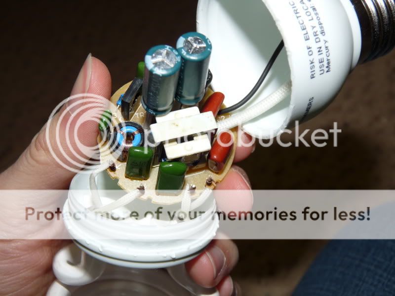
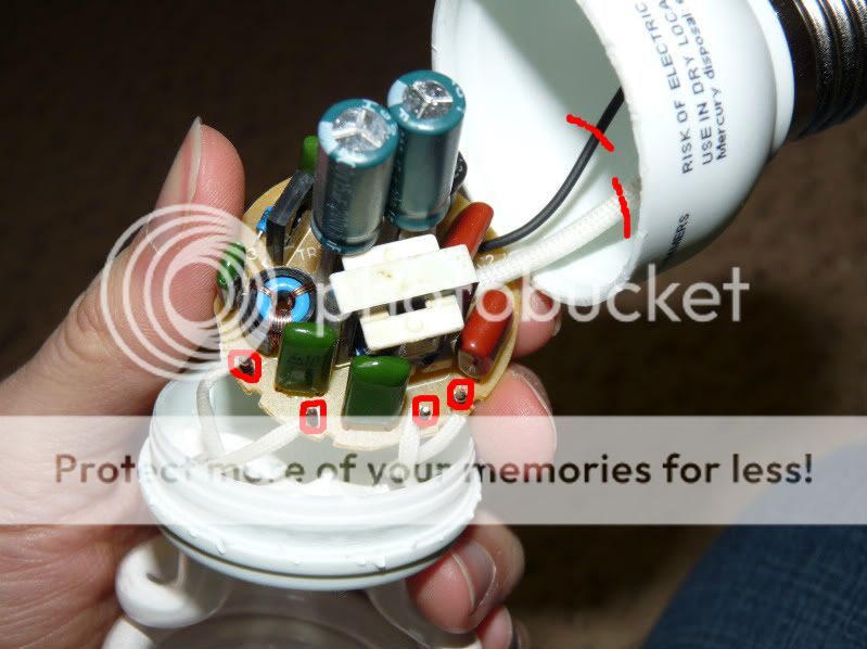
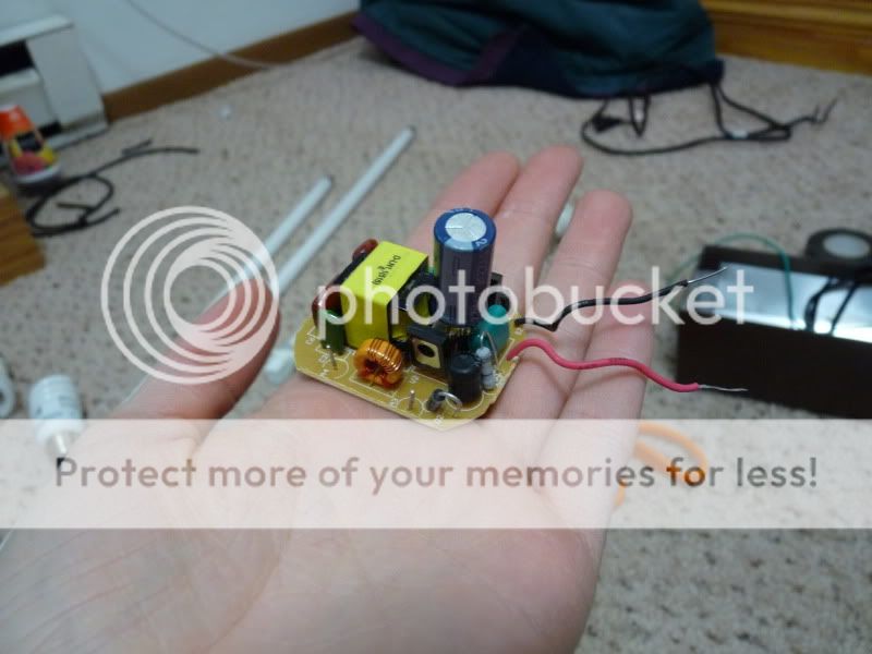
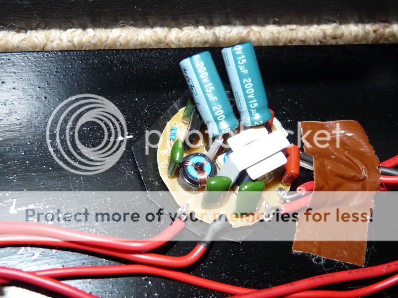
Above is a westinghouse 23 watt ballast. All the brands I have taken apart are very similar. Westinghouse and Sylvania I prefer over GE, but all brands will work. To those familar with lights the wiring shown on the CFL in the pic will look very similar to a normal ballast. The ballast has two wires for power and these need to be cut. Two brands, Westinghouse and Sylvania, have a resistor that is kinda hidden in a white tube (can see it in the pic). Try not to cut it off, but if you do its easy to just reattach. Then their are 4 small pins on the ballast that have wires wrapped around them and run to the bulb. These need to be unwrapped and the ballast is free.
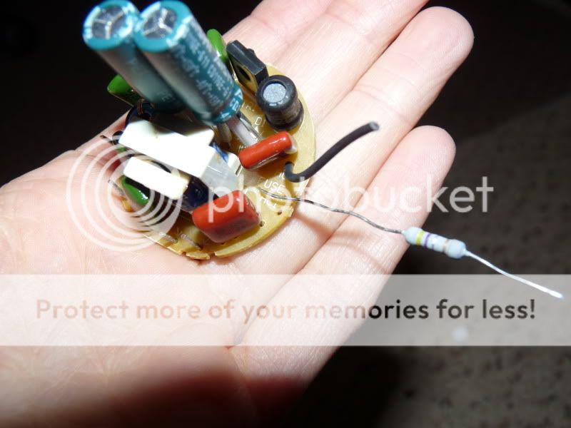
These are examples of removed ballasts.
Step 2: wiring! (Its not as hard as it seems. Honestly!)
Now the little pins on the ballast are always together in pairs, either on opposite sides or offset from each other. Wiring these ballasts to a different bulb is as simple as attaching wires to the pins and running them to the pins on the bulb. One pair of the pins runs to one end of the bulb and the other pair goes to the other end of the bulb. The exact pins you connect to on each end of the bulb DOES NOT matter. This makes the wiring very simple as multiple ways are correct. The two power wires can be connected directly to a standard AC power cord. If you don't have one buy a $1 extension cord and cut the socket end off it.
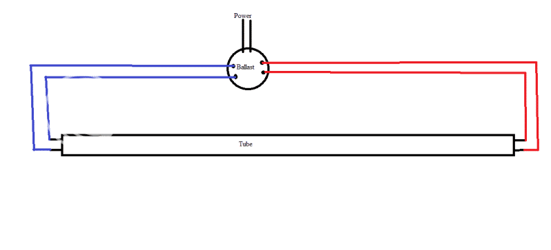
This is a simple wiring diagram. I color coded it to show which wires are interchangeable. Basically if you cross the two red wires with eachother is doesn't matter, same with the two blue wires, or the two black ones. It will work regardless. However if you cross two different colors, a blue and a red, it will not light. But you will NOT damage the ballast either if you by chance mess this up. These ballasts like all ballasts use high voltage. Safest way to work with them is do NOT touch it if it is plugged in, this goes for all electrical work.
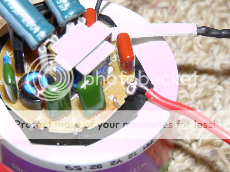
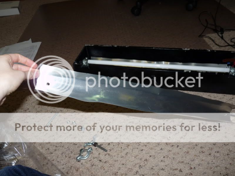
Connecting wires to the pins is the trickiest part, but still not very hard. I could careless what wire you use, but every light fixture I have taken apart uses primary wire, 18 AWG(american wire gunge) rated up to 300V. I prefer to use this type of wire, but have occasionally used lesser rated wires. You can get it at most home improvement stores usually $5 for more then enough. This wire is often solid core. I CAREFULLY bend the pins on the ballast till they form an almost closed hook. Make a similar closed ring with the wire, then stick the two together and bend it so they are both fully closed. The tighter the better, a lose connection is more likely to make the fixture flicker when it is moved.
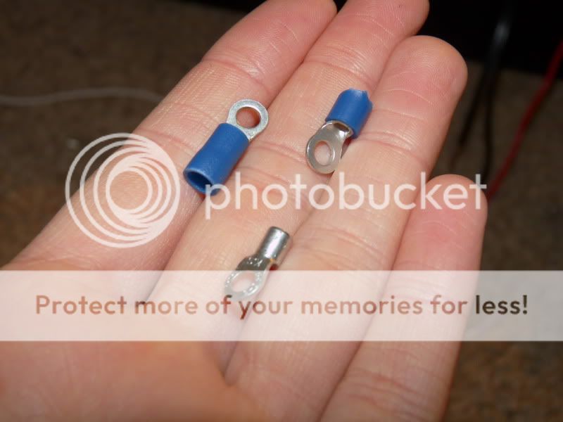
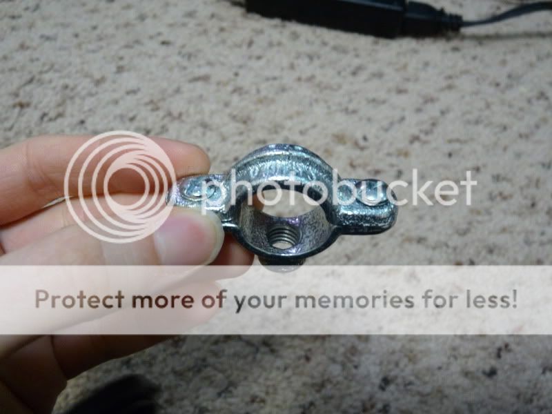
Now there are two ways to connect the wires to the pins. Either with endcaps/socket or making a DIY connection with terminal rings. Proper sockets are much more preferred, but with T5 it is doubtful you will find these locally. I would suggest getting them online along with the bulbs or using the terminal rings. The terminal rings are not as convenient as the twist sockets, but get the job done regardless. Its harder to get the bulb in and out, but its not like this is done very frequently. The ring terminals are super cheap($1 for 2 dozen), but you do need to buy extra parts for mounting the bulb.
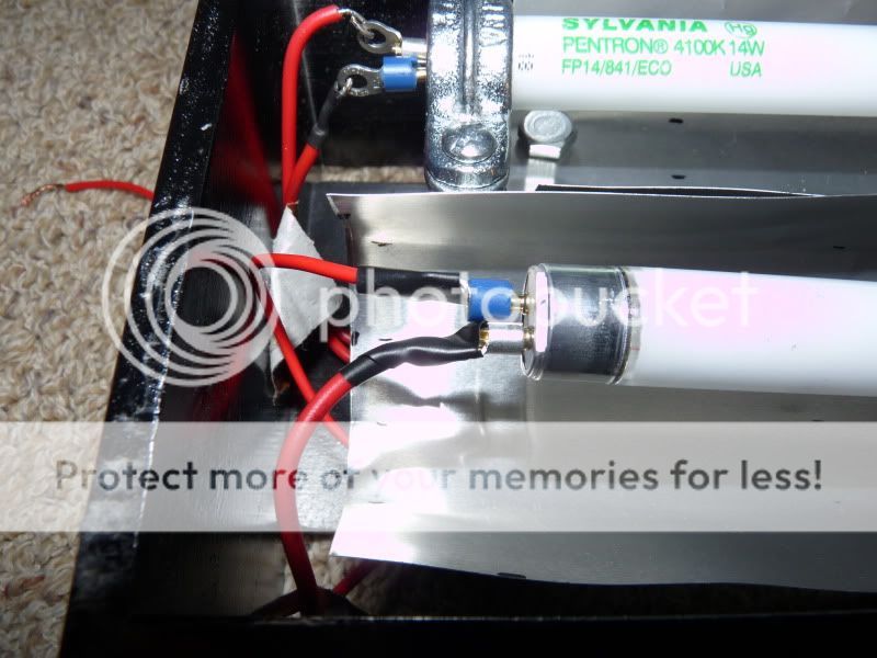
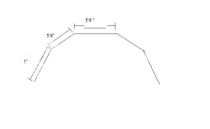
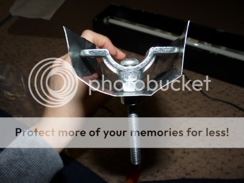
If you use ring terminals they should be 16-14 AWG size, as this size fits snugly over the bulb pins. You need to trim the insulation on them down so they are shorter. If you are using T5 bulbs half of them need the insulation fully removed or they won't fit. For T8s or PC bulbs leave the insulation on.
Then connect the wires from the ballast to the ring part of the terminal. Then each terminal fits on a pin. The rear bulb shows you how they are wired. Once you are done the connection should be covered like the front bulb has, to avoid to a connection between the two wires.
Once you attach a powercord to the ballast your basically done with wiring. Below are a few examples.
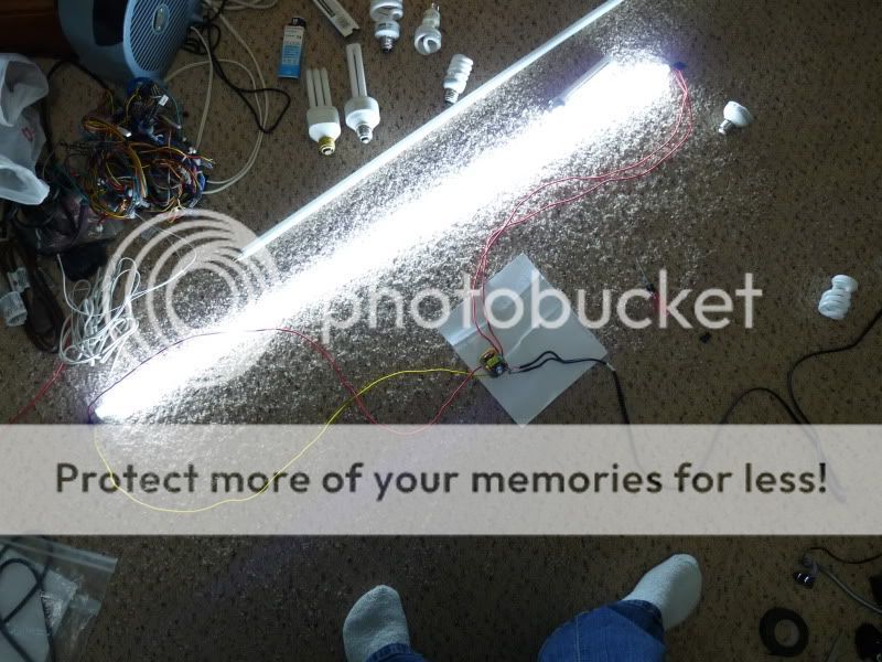
This is a 4 ft Normal output T5 with a 26 watt ballast.
A 14 watt NO T5, but running off a 23 watt ballast making it basically a HO T5. I plan to swap out the bulbs when ever I get around to ordering HO bulbs.
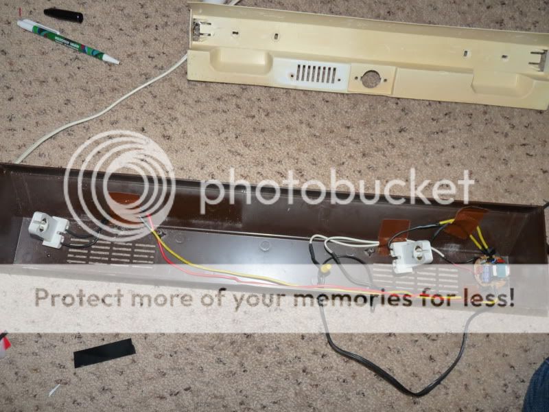
Retrofit into a standard T8 light strip, using the existing hardware. I've been using this fixture for a month and a half without any issues. The only difference you can notice is instant start up, no high pitch buzzing, and the fixture is at least 50% lighter in weight.
Okay tired of typing for now, but more to come!
To start with I have been using CFL ballasts to power linear tubes. By CFL I mean the spiral energy saver bulbs. This takes the cost of the ballast from being one of the most expensive part of a fixture to about $1-3. However it only works well with wattage below 23-26 watts since these are the more common larger sizes of CFL bulbs. You can certainly go higher, but the cost jumps quiet a bit. (for example 40 watt spiral CFLs tend to go for $8-10). This method also works best with T5 bulbs, these are closest to the diameter of the spiral compacts and also one of the more efficient linear tubes. However it is not limited to T5 bulbs, it works with T8's or power compacts. This method allows for a lot of customization including underdriving or overdriving bulbs, but I will go into more detail later.
I will only briefly cover mounting a fixture. Mainly because this is very variable depending on how you are mount the bulbs and to what.
First we will start with a brief overview of fluorescent lights. T8, T5, PC bulbs are all very similar in construction. The bulbs are powered by ballasts, which increase the voltage required to start the bulb. Wires then run to each pin of the bulb. They are pretty simple overall. The wiring can vary a bit depending on the individual ballast used. This is a general diagram of a linear bulb fixture.
Also common with T8 fixtures are the "starter" type. These function similar as above, except instead of a ballast they have a transformer. The Starter is a capacitor that functions to increase the voltage required to start the bulb.
Now for building your own fixture!
Step 1: locate a ballast
As I mentioned above I have been recently experimenting with using Spiral CFL ballasts to power other bulbs. This greatly decreases the cost of the fixture. You need to buy a spiral CFL with the proper wattage you want. For T5's and PC bulbs the wattages are basically equivalent. Example a 14 watt CFL ballast will power a 14 watt T5 at around its normal output. For T8s however I have found you need a higher wattage ballast then the wattage stated on the bulb, example a 23 watt CFL ballast to power a 15 watt bulb. This is because of the larger diameter of the bulb. I personally would stick with T5s or PC bulbs, but if you have a T8 fixture with a dead ballast this is certainly a cheap way to get it up and running again. These are electronic ballasts and run very quiet and provide instant start up on all bulbs I have tried.
To get a spiral CFL ballasts you need to take apart a spiral CFL. This is very simple and poses no danger as long as you don't break the bulb. Take a screwdriver and run it along the seam on the base of the bulb. I found its easy to run it all the way around the bulb just separating the two parts. Then start prying them apart. Eventually the base should pop open and reveal the ballast.
Above is a westinghouse 23 watt ballast. All the brands I have taken apart are very similar. Westinghouse and Sylvania I prefer over GE, but all brands will work. To those familar with lights the wiring shown on the CFL in the pic will look very similar to a normal ballast. The ballast has two wires for power and these need to be cut. Two brands, Westinghouse and Sylvania, have a resistor that is kinda hidden in a white tube (can see it in the pic). Try not to cut it off, but if you do its easy to just reattach. Then their are 4 small pins on the ballast that have wires wrapped around them and run to the bulb. These need to be unwrapped and the ballast is free.
These are examples of removed ballasts.
Step 2: wiring! (Its not as hard as it seems. Honestly!)
Now the little pins on the ballast are always together in pairs, either on opposite sides or offset from each other. Wiring these ballasts to a different bulb is as simple as attaching wires to the pins and running them to the pins on the bulb. One pair of the pins runs to one end of the bulb and the other pair goes to the other end of the bulb. The exact pins you connect to on each end of the bulb DOES NOT matter. This makes the wiring very simple as multiple ways are correct. The two power wires can be connected directly to a standard AC power cord. If you don't have one buy a $1 extension cord and cut the socket end off it.
This is a simple wiring diagram. I color coded it to show which wires are interchangeable. Basically if you cross the two red wires with eachother is doesn't matter, same with the two blue wires, or the two black ones. It will work regardless. However if you cross two different colors, a blue and a red, it will not light. But you will NOT damage the ballast either if you by chance mess this up. These ballasts like all ballasts use high voltage. Safest way to work with them is do NOT touch it if it is plugged in, this goes for all electrical work.
Connecting wires to the pins is the trickiest part, but still not very hard. I could careless what wire you use, but every light fixture I have taken apart uses primary wire, 18 AWG(american wire gunge) rated up to 300V. I prefer to use this type of wire, but have occasionally used lesser rated wires. You can get it at most home improvement stores usually $5 for more then enough. This wire is often solid core. I CAREFULLY bend the pins on the ballast till they form an almost closed hook. Make a similar closed ring with the wire, then stick the two together and bend it so they are both fully closed. The tighter the better, a lose connection is more likely to make the fixture flicker when it is moved.
Now there are two ways to connect the wires to the pins. Either with endcaps/socket or making a DIY connection with terminal rings. Proper sockets are much more preferred, but with T5 it is doubtful you will find these locally. I would suggest getting them online along with the bulbs or using the terminal rings. The terminal rings are not as convenient as the twist sockets, but get the job done regardless. Its harder to get the bulb in and out, but its not like this is done very frequently. The ring terminals are super cheap($1 for 2 dozen), but you do need to buy extra parts for mounting the bulb.
If you use ring terminals they should be 16-14 AWG size, as this size fits snugly over the bulb pins. You need to trim the insulation on them down so they are shorter. If you are using T5 bulbs half of them need the insulation fully removed or they won't fit. For T8s or PC bulbs leave the insulation on.
Then connect the wires from the ballast to the ring part of the terminal. Then each terminal fits on a pin. The rear bulb shows you how they are wired. Once you are done the connection should be covered like the front bulb has, to avoid to a connection between the two wires.
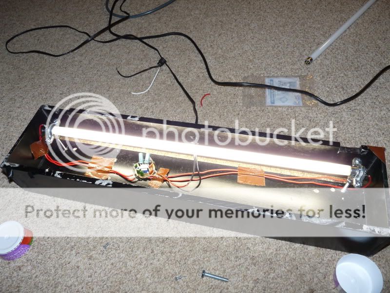
Once you attach a powercord to the ballast your basically done with wiring. Below are a few examples.
This is a 4 ft Normal output T5 with a 26 watt ballast.
A 14 watt NO T5, but running off a 23 watt ballast making it basically a HO T5. I plan to swap out the bulbs when ever I get around to ordering HO bulbs.
Retrofit into a standard T8 light strip, using the existing hardware. I've been using this fixture for a month and a half without any issues. The only difference you can notice is instant start up, no high pitch buzzing, and the fixture is at least 50% lighter in weight.
Okay tired of typing for now, but more to come!

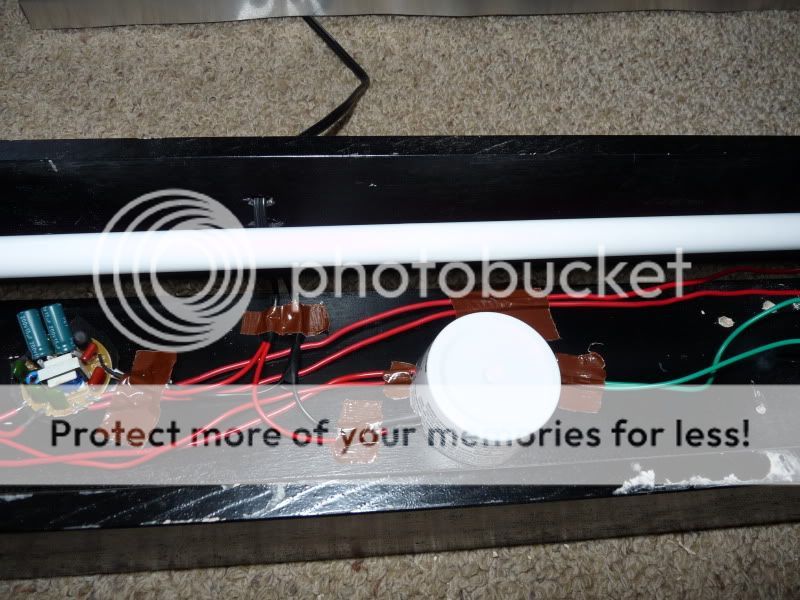
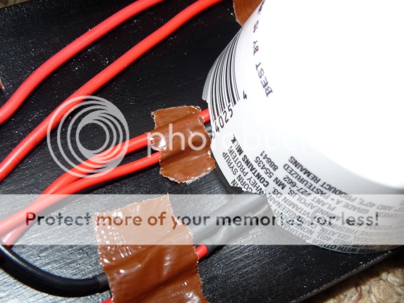

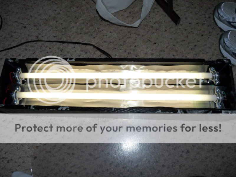
 Total cost was about $30 including the bulbs, but not including the wooden housing. Dual T5 HO at around 46 watts total.